PIC32MX1xx & PIC32MX2xx Getting Started (under destruction)
Microchip PIC32MX1xx/2xx:
This is about getting started with Microchip Technology's PIC32 32-bit microcontroller family.
Microchip purchased Atmel awhile back and offers 32-bit microcontrollers from Atmel's
AVR32 and ARM families as well as Microchip's own MIPS4000-based 32-bit PIC32
families. At the mid-low end of the PIC32 world is the PIC32MX1xx and 2xx series...
Here are some high points:
#2: http://chipkit.net/chipkit-bb32/ (dead link sorry)
This example is very similar to #1 above but provides a Microchip standard 6-pin, 0.1" pitch,
ICSP header interface for programming/debugging instead of the USB interface. It adds a
light-dependent resistor, or LDR, and an extra LED. Kudos again to the chipKIT/MPIDE
Development Team.
#3: http://fubarino.org/index.html (dead link sorry)
You can buy a PIC32MX250F128B pre-programmed with the enhanced USB Bootloader from
MicrochipDIRECT for $5.17USD each + shipping:
So here's what I've built:
[ Minimal System #1 ]

If I get a chance, I'll add a schematic but you can get the needed information for the ChipKit and
Fubarino examples cited.
This is about getting started with Microchip Technology's PIC32 32-bit microcontroller family.
Microchip purchased Atmel awhile back and offers 32-bit microcontrollers from Atmel's
AVR32 and ARM families as well as Microchip's own MIPS4000-based 32-bit PIC32
families. At the mid-low end of the PIC32 world is the PIC32MX1xx and 2xx series...
Here are some high points:
- Program Flash
- PIC32MX270F256B has 256kB flash
- PIC32MX250F128B has 128kB flash
- Data RAM:
- PIC32MX270F256B has 64kB RAM
- PIC32MX250F128B has 32kB RAM
- 40MHz and 50MHz versions
- USB (incl. "USB-on-the-Go")
- Single-cycle 32x16-bit multiply; 2 cycle 32x32-bit multiply
- 2, SPI/I2S ( Great for Codec interface for audio or radio projects )
- 2, I2C
- 2, UART
- GPIO w/ some remappable pins
- Timers aplenty
- PKGs: SSOP28, SOIC28, SPDIP28, VTLA36, VTLA44, QFN44, & TQFP44
Minimal Systems:
"Minimal systems" are the simplest and therefore probably the quickest DIY way to try out a microcontroller
(or microprocessor). They involve as few components as possible to get some kind of test programs to run on
some target hardware ( e.g. blink an LED and maybe sense a switch closure ).
Excellent realizations of PIC32 minimal systems by the chipKIT (tm) people are nicely described/documented at:
#1: http://chipkit.net/diy-chipkit-board/ (dead link sorry)
In this case an SPDIP28 PIC32MX250F128B is plugged into a solderless breadboard
with a very few other components to form a system programmable via USB ( using a USB
"bootloader" programmed into the PIC32MX250F128B ). The authors used Microchip's freely
downloadable Multi-Platform IDE (MPIDE) to "upload" ( move from development PC to the
embedded target system ) compiled sketches ( very Arduino-like if not exactly Arduino
compatible ) via the enhanced USB bootloader in the PIC32MX250F128B.
A very nicely realized solution by the chipKIT/MPIDE Development Team.
This example is very similar to #1 above but provides a Microchip standard 6-pin, 0.1" pitch,
ICSP header interface for programming/debugging instead of the USB interface. It adds a
light-dependent resistor, or LDR, and an extra LED. Kudos again to the chipKIT/MPIDE
Development Team.
#3: http://fubarino.org/index.html (dead link sorry)
The Fubarino Mini is basically a chipKIT board ( #1 in this list ) using a PIC32MX250F128B
in a VTLA44 pkg on a 40-pin DIP carrier board with 0.6" left/right spacing exactly like a
classic 40-pin DIP IC. The Fubarino Mini's PIC32 is pre-loaded with the enhanced PIC32 USB
bootloader just like the two examples above in this list so the programming/debugging interface
is also by USB. The chipKIT (tm) "Fubarino Mini" Development Board (MicrochipDIRECT
Part Number: TCHIP011 costs $22 + shipping and is available at:
https://www.microchipdirect.com/product/search/all/TCHIP011
Descriptions, schematics, etc. can be found at:
https://www.microchip.com/Developmenttools/ProductDetails/TCHIP011
You can buy a PIC32MX250F128B pre-programmed with the enhanced USB Bootloader from
MicrochipDIRECT for $5.17USD each + shipping:
Product ID = TCHIP-USB-MX250F128B
URL = https://goo.gl/E1Undn
URL = https://goo.gl/E1Undn
Debugging Sketches:
The combination of the pre-programmed enhanced USB bootloader and MPIDE provide a programming
and debugging environment where Arduino sketches and other code can be written and debugged.
and debugging environment where Arduino sketches and other code can be written and debugged.
I use Microchip's embedded development IDE called MPLABX (also a free download) for everything
from the PIC10F series to PIC32MZ series. I bit the bullet a few years back and bought an ICD-2
( superceded by the ICD-3 which, in turn, has been superceded by the ICD-4). The PICkit, PICKit-2,
PICkit-3, and now PICkit-4 ( $48USD from Microchip ). One could argue that with ST-Link 2 dongles
on eBay for < $3USD, that Microchip's PICkit-4 is expensive at $48USD and they'd be darned right.
There are as well clones on eBay, Alibaba, AliExpress, etc reaching the sub $20USD range (incl. shipping) as well as DIY versions (e.g. https://reviahh.wordpress.com/2016/01/31/making-a-pickit-3-clone/)
My PIC32 DIY Hardware Projects thus far:
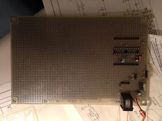
[ Minimal System #1 ]

The processor is an SPDIP28 PIC32MX250F128B In the first example I soldered and epoxied an RJ-12
socket on the perfboard in order to connect my ICD-3 debugger to provide single-step or breakpoint-based
interactive debugging.
[ Minimal System #2 ]

The SOIC28 carrier soldering was an early attempt and is veercocked but actually works fine.
In both cases the processor is a PIC32MX250F128B in SPDIP28 or SOIC28-on-carrier.
The SOIC28 carrier soldering was an early attempt and is veercocked but actually works fine.
In the first example I soldered and epoxied an RJ-12 socket on the perfboard in order to connect
my ICD-3 debugger to provide single-step or breakpoint-based interactive debugging.
In the second example I just connected an RJ-12 plug to 6x1 Dupont female cable assembly to a
5-pin male 0.1" pitch header for ICD-3 connection. Both implementations take 5V through an
LDO to create 3.3V and add very similar wiring and decoupling capacitors as the ChipKit and
Fubarino instances above to create a hardware platform. Because I did not use USB I was able
to use the PIC32MX's internal RC oscillator freeing up some more pins.
If I get a chance, I'll add a schematic but you can get the needed information for the ChipKit and
Fubarino examples cited.
73's
Coop, AA1WW
Comments
Post a Comment